bookmark_borderRemote control wheelbarrow with tracks

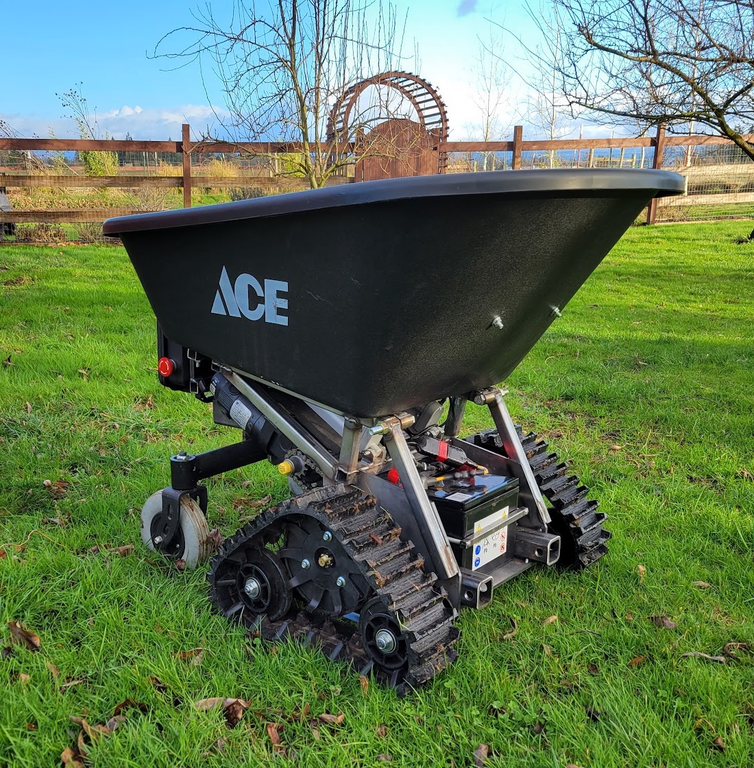
Here’s a new project I’m working on – a RC wheelbarrow on tracks. It’s exactly what you would expect.

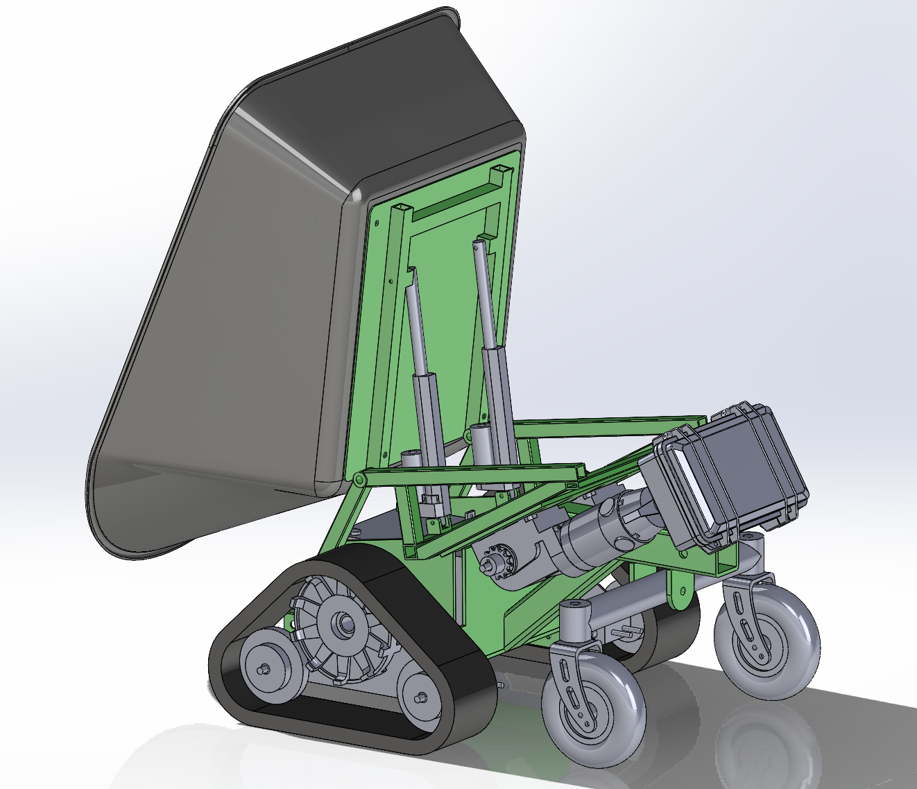
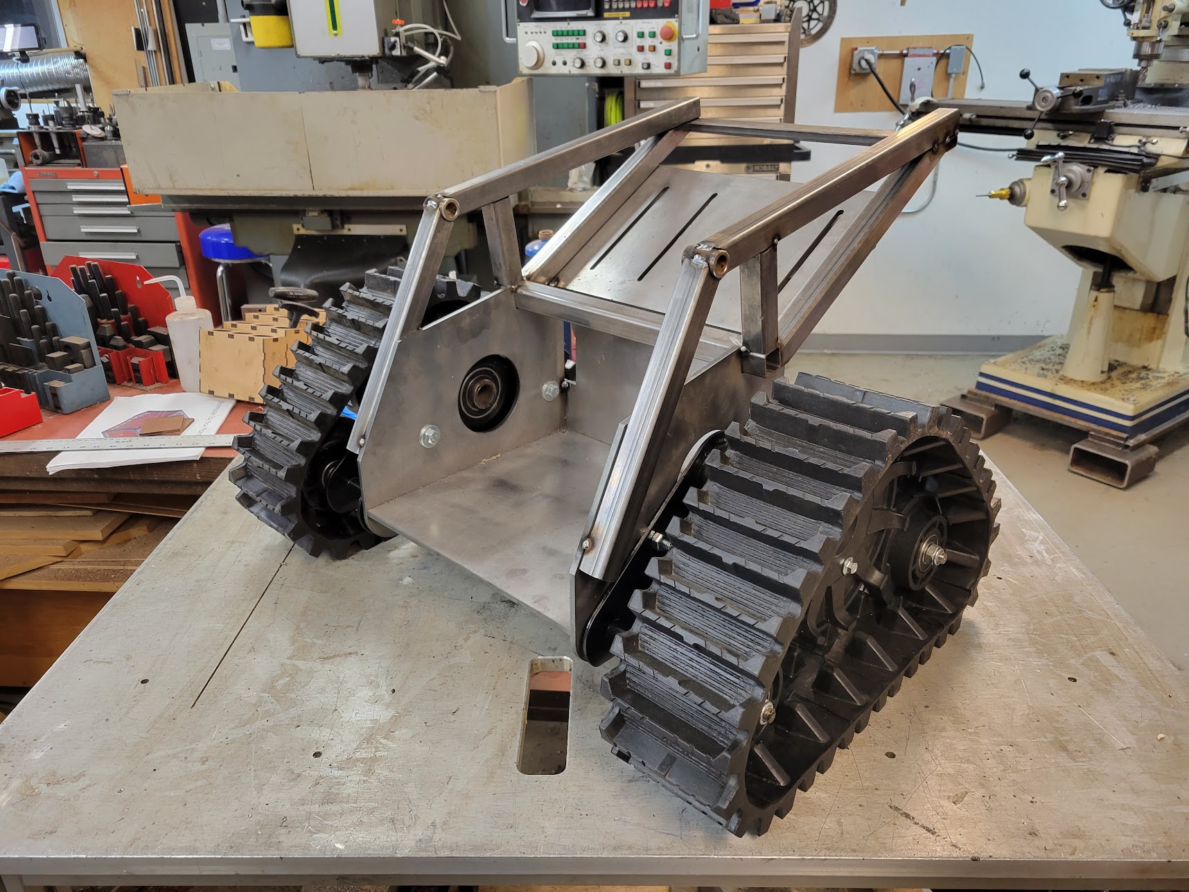
I took some time to model all of the different parts in Solidworks – the motors, tracks, casters, wheelbarrow, actuators, etc. – then I arranged them in an assembly and designed the chassis that I would need to fabricate afterwards. In the image above the gray stuff was all existing parts I sourced and the green was what I would need to fabricate. This was time consuming, but it did make the build a lot more straightforward. I had the flat parts laser cut locally from 1/4″ steel plate and used tabs/slots for alignment, this worked out great and was not that much more expensive that the raw material in the first place.

The tracks

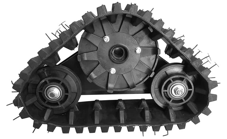
The basis for this are these rubber tracks. I noticed them on ebay/amazon and the usual overseas sites at least a year ago and have had this idea in my head since then. They seem like they’re intended for small ATVs, but the listings are all a bit sketchy – you can buy the tracks alone or with an axle, sprocket, and brake rotor. The drive sprocket uses splines, so I bought the set with the axle for ~300 dollars just so that I didn’t have to try machining my own like these guys did, in fact it was only after I watched that video that I decided to finally order them.

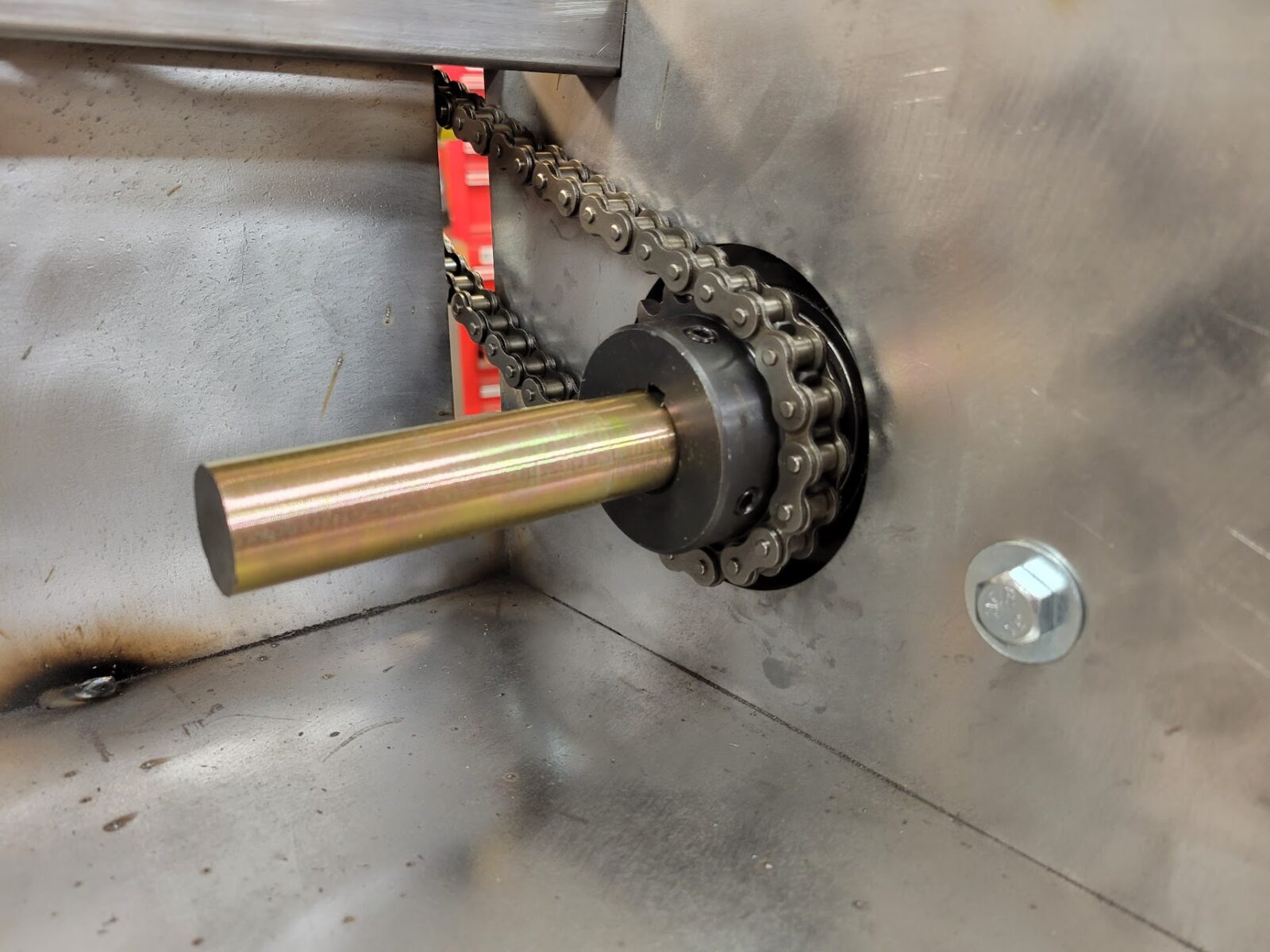
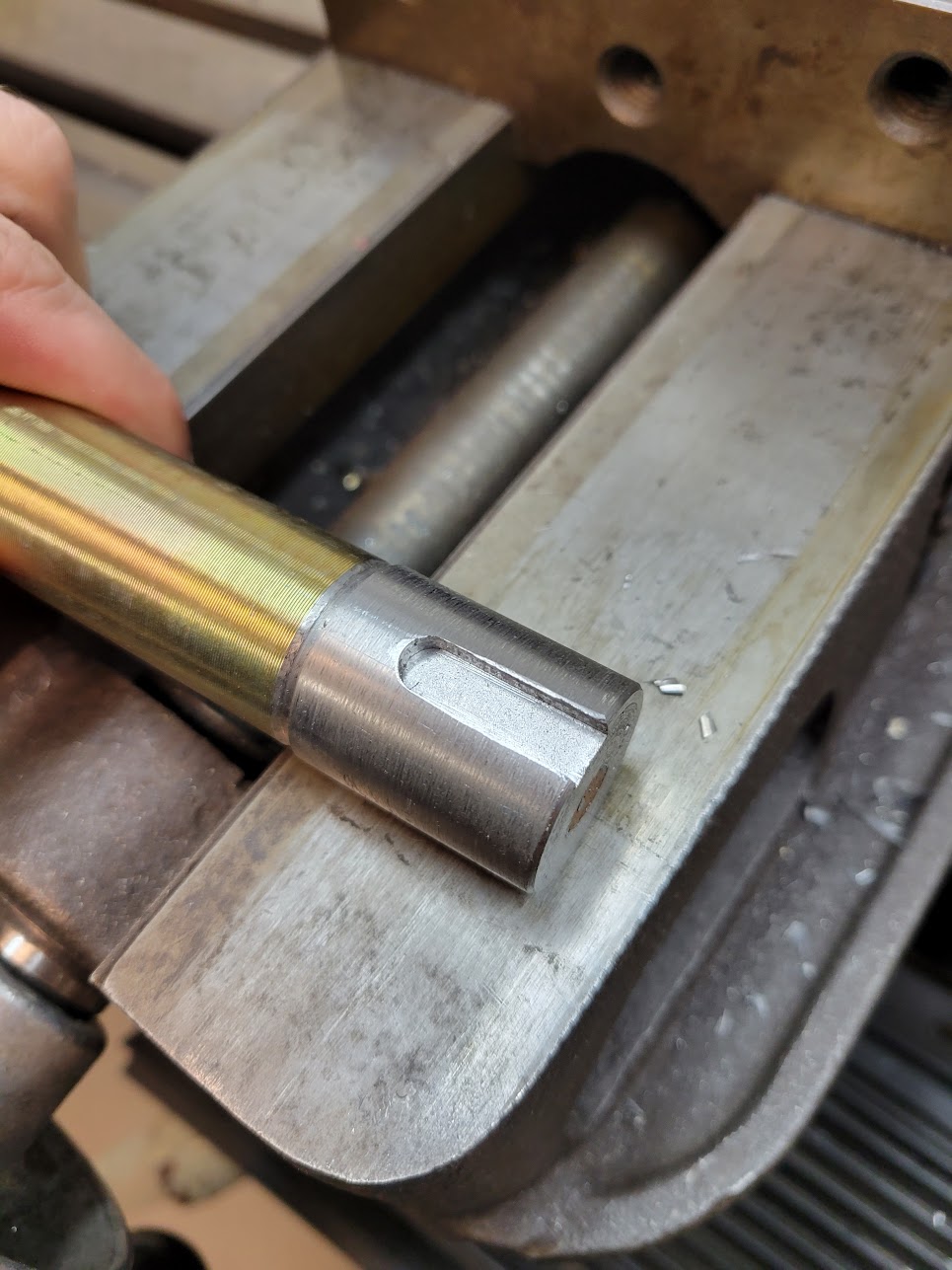
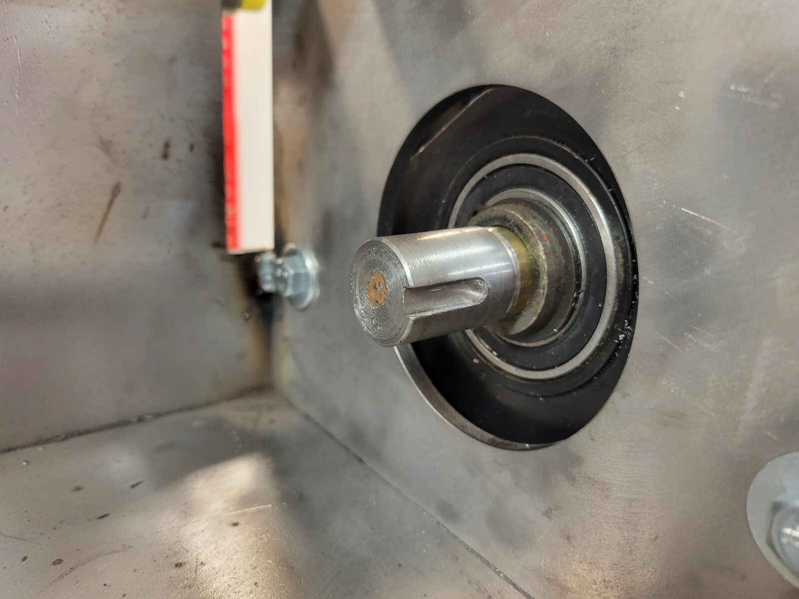
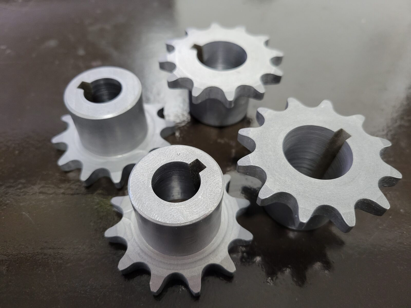
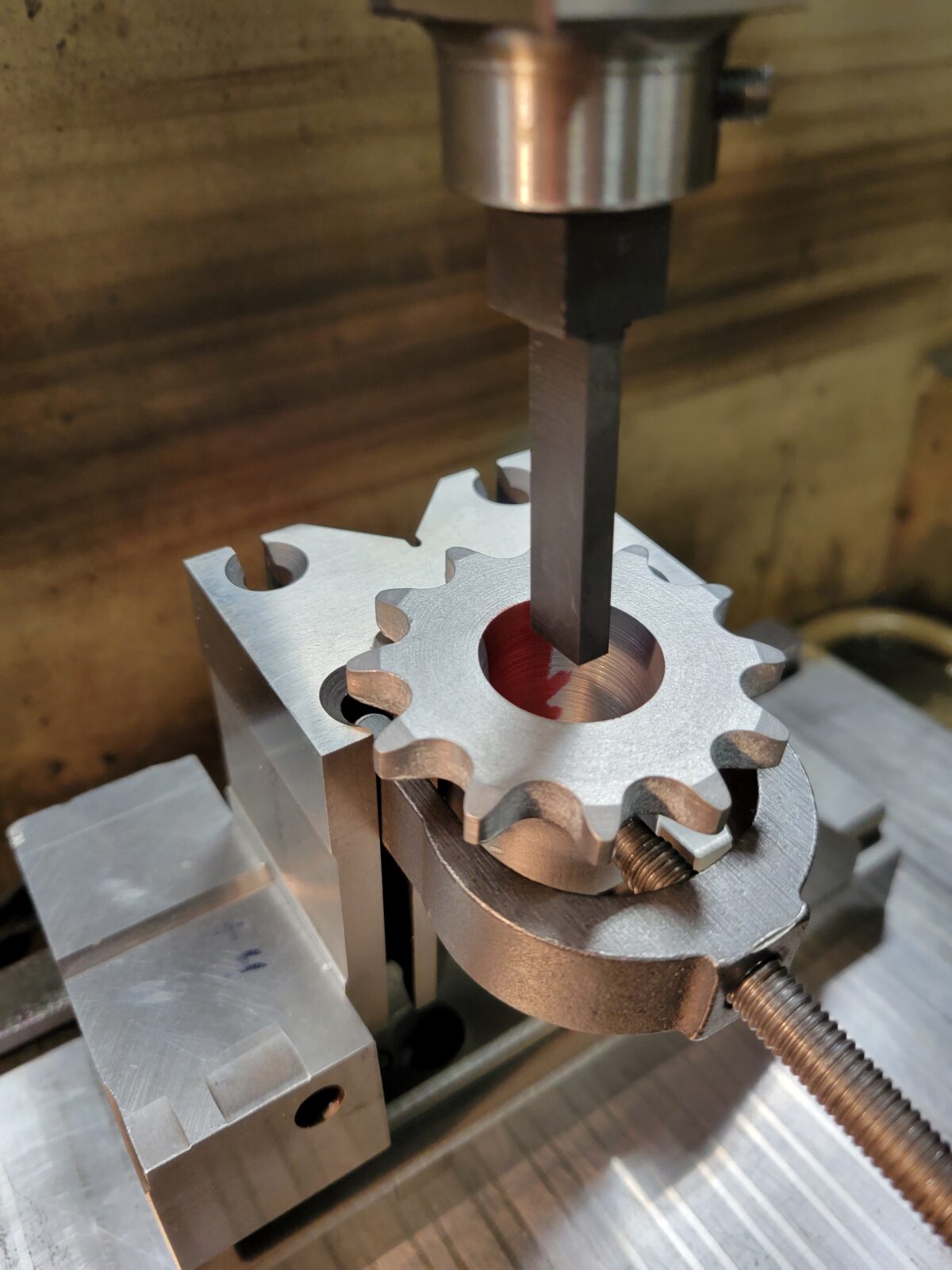
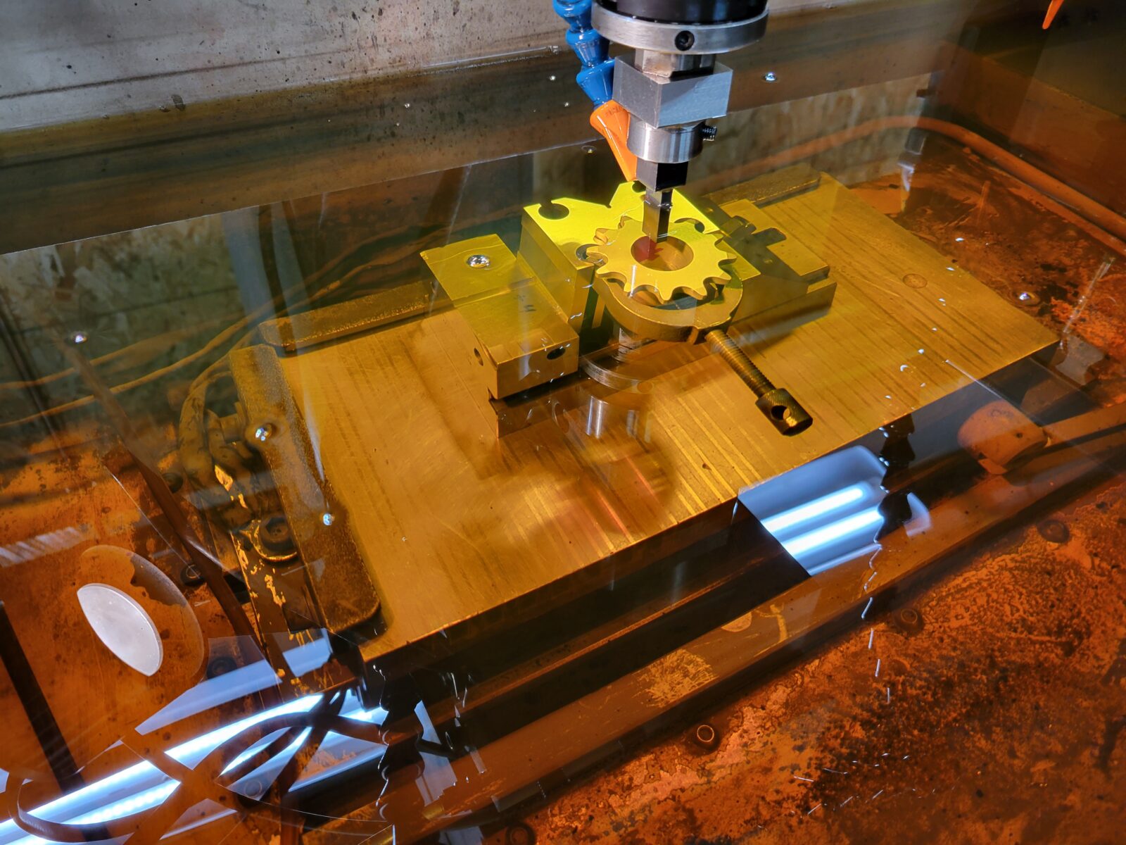
I sliced the axle in half and am driving it using off-the-shelf sprockets with a 1″ bore, but unfortunately the axle is metric and just a bit too small. I welded on a sleeve, turned it to size, and added a keyway. I could have used sprockets with a smaller hole and bored it to size, but cutting a slot on a shaft was easier than broaching one in a bore for me. Driving the chain is a wheelchair motor, the gear ratio is 12:18 which trades some top speed for increased torque. The motors have tapered shafts, there wasn’t an easy sprocket to buy for that end so I made my own (there’s a little more about that here).

Electronics

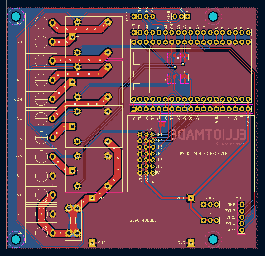
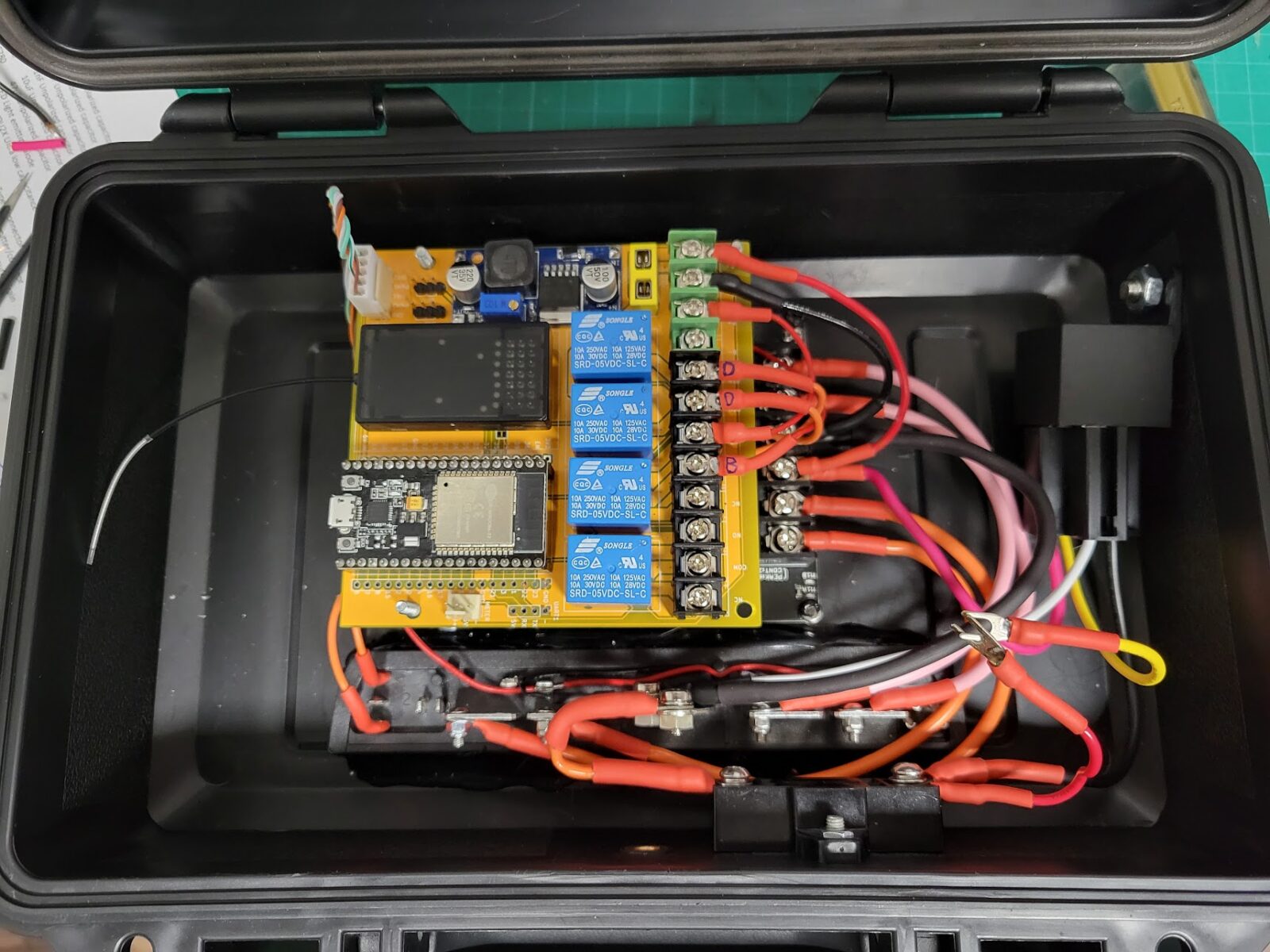
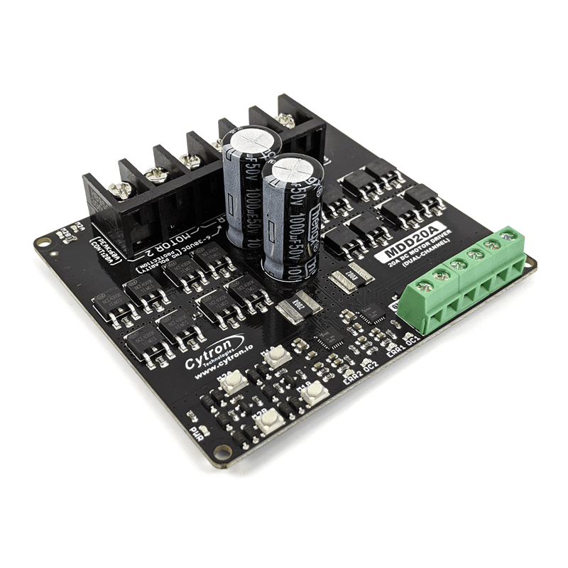
The magic happens inside of this plastic box. The robot uses two 12v lead-acid batteries in series and the motors are driven with the Cytron MDD20A board. I found this to be a decent and cheaper substitute for the Sabertooth 2×32 that I have used previously – it doesn’t have any smarts onboard so it takes a few more pins and a bit more code to interface with, but it seems to handle the job just fine. I use an ESP32 to run the show – it interfaces with the motor controller and the RC receiver and makes everything work together. The circuit board (yellow) above is of my own design, it has a 5v power supply and a set of relays for switching the various functions – like the brakes and dump actuators.

Remote control

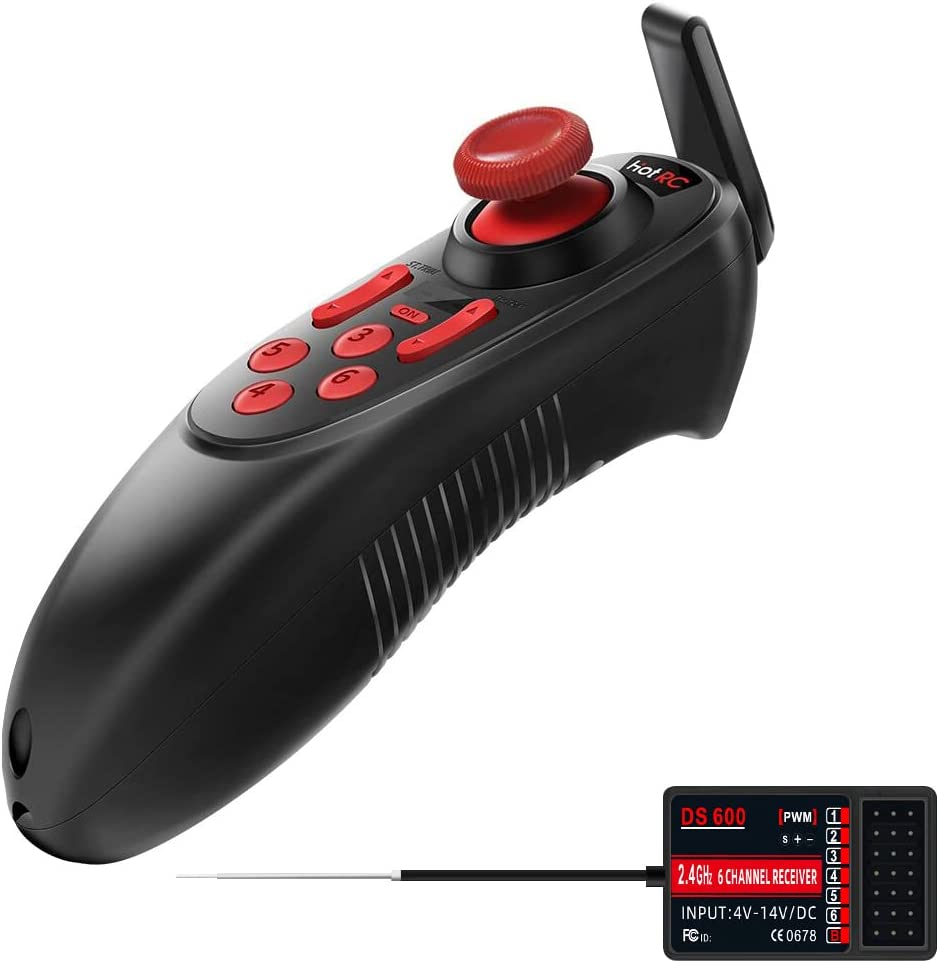
The remote is a critical part of making this practical. It’s meant to be a little buddy that hauls stuff around for you, and for that reason it’s not reasonable to use a traditional RC transmitter – the kind with a big antenna, two joysticks, and lots of switches. My main requirement was to have something that fit in my pocket and that really limited the options. Initially I planned to hack a Wii nunchuck controller, but then I found the DS-600. It’s made for boats (I think?) and has some weird quirks and limitations, but crucially it has the form factor I needed.

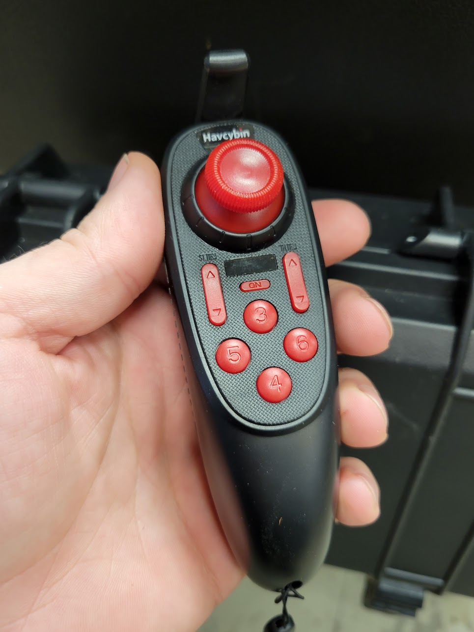
If you want to use this… be warned that it is pretty funky. It does have the ability to trim each axis on the joystick, but you can’t adjust dead zones, maximums, etc. Very bare bones. I did all of this in code on the ESP32. Three of the face buttons are latching (toggle) and one is momentary, this is actually pretty limiting. For example, I want to use the joystick for driving the tracks, and separately I want to control the dump function: up and down. If there were two momentary buttons I could easily make one go up and the other go down, no problemo. Since there is only one, I used one of the latching buttons to change a “mode” in the ESP32, then I can remap a joystick channel to the dumper. This solves the problem but also means I can’t drive and move the dumper at the same time. I used the same approach for an even more important function: disabling the joystick entirely. The ESP has a mode that disables all movement of the machine unless one of the latching channels is “on” – enabling this lets you operate the machine, and disabling it makes it safe to put the controller in your pocket without sending bogus commands if you bump the joystick; without this the whole thing would be too inconvenient or dangerous to be practical.

bookmark_borderCutting a keyway in a tapered bore with an EDM

Slowmo shot of cutting a keyway on a CNC EDM. Definitely overkill, but easier than broaching the keyways on a taper for these sprockets:

These are for a remote control wheelbarrow project I’ll share later. For setup the sprocket was put in a v-block and tilted so the taper angle was vertical. The graphite electrode is just a long rectangle. This was done on a CNC EDM, not a sinker, so we went to full depth, burned in from the front, then burned into the corners to get to the final width.

bookmark_borderMixed berry cider: Brew Berrymore

This is a batch of cider made with just blackberries, raspberries, and blueberries. The image was generated by stable diffusion.

  • 9/10
    • Started with:
    • 3 lb blueberries
    • 6 lb blackberries
    • 5 lb raspberries
    • 6.5 lb sugar
    • Water to reach 5 gallons
    • Starting gravity: 1.060
  • 9/11
    • Added yeast: Safale S-04
  • 9/16
    • Fermentation was pretty slow, removed the fruit solids and racked to a carboy
    • Gravity: 1.050
  • 10/8
    • Racked and added sparkolloid
    • Final gravity 0.995 for ~7.2%
  • 10/14
    • Added 3 oz priming sugar, target is 2 volumes of Co2
    • Ended up with 4.2 gallons in the end
    • Bottled and labeled
Fermentation
Kept the fruit in a bag which made it much easier to separate the solids later

bookmark_borderCircuitpython + Pi Pico: saving settings at runtime without an EEPROM

Unlike some other microcontrollers, the RP2040 doesn’t have any EEPROM onboard. On something like the ATmega328P for example, it is easy to save the value of a variable to the EEPROM so that you can read it back on the next boot; this is handy for remembering a user setting or recalling the last state your project was in between power cycles. I have used this in the past with some of my word clocks so that when it is powered up it will “remember” the last color setting.

So, how to do this with something like the Raspberry Pi Pico? The solution I am putting forth uses the flash storage where the program files and libraries are stored. I didn’t invent this idea, but didn’t find everything I was looking for very easily so decided I would write it down here. The main idea comes from Adafruit: https://learn.adafruit.com/cpu-temperature-logging-with-circuit-python/writing-to-the-filesystem

A couple points on this solution:

  1. Limited write cycles: Flash memory has a limited number of write cycles before it wears out, so be conscious of this. A good strategy is to only write when something meaningful is changed, or if you are logging data to a file consider the interval and pick something reasonable. If you write on every loop of your program you could accelerate the failure
  2. Only one device can write files at a time: Files on the device are generally only available to be written by one device at a time. Normally the files are read-only for the microcontroller – it can read them but not change them during operation, and the files are read/write for a computer if it is mounted as a USB device.
  3. Write permissions are only changed on boot: switching the read/write permissions on the filesystem only happens when the microcontroller boots up. A reset doesn’t count, so resetting via software, the REPL, or writing a new file doesn’t do the trick – the setting is made when it powers up. This means this isn’t a good solution if you wanted to have both a PC and the microcontroller writing to the same (or two separate) files at the same time.
  4. When the microcontroller has write access, you cannot upload new code: This means that in order to update the device with new code, you need a way to switch the access – like a switch or jumper. If you accidentally end up locked out, check the Adafruit link above and there’s a note on how to fix this via the REPL.

How to do it:

First, create a JSON file that will contain the settings. Here is the example I’m using:

{"color": "Red", "brightness": 0.1, "mode": 1}

Second, the filesystem permission needs to be set at boot time, the code below needs to be in the “boot.py” file. In this example I’m using GPIO 17: when the pin is low at boot, the microcontroller has write access, and when it is high the PC will have write access. You could reverse this so the default behavior matches your requirement.

import board
import digitalio
import storage

switch = digitalio.DigitalInOut(board.GP17)
switch.direction = digitalio.Direction.INPUT
switch.pull = digitalio.Pull.UP

# If the GP17 is connected to ground with a wire
# CircuitPython can write to the drive
storage.remount("/", switch.value)
print(switch.value)

Third, in “code.py”, you can treat the filesystem like you might with python on any other system. I like to use a JSON file because it gives an easy structure to work with for things like settings, but once you are able to open and write files you can do whatever you want. In this example I’m reading the file, changing one value, then overwriting it.

#If the device boots up and has access to the filesystem, you should observe that the value for
#color in the settings.json file is "blue".  You will also be unable to modify or upload files

#If it boots up and the PC has write access to the filesystem, the serial monitor will show
#an error, and the contents of the file won't be modified

import json

#open the settings file, read the JSON into an object named "data", then close it
with open("settings.json") as infile:
    data = json.load(infile)
    print(data["color"])
infile.close()

#change one of the values in "data"
data["color"] = "Blue"

#finally, open the file again and overwrite it with the current contents of "data"
with open("settings.json", "w") as outfile:
    json.dump(data, outfile)
outfile.close()

Result

When this code all runs, the result should be that the JSON file now looks like this:

{"color": "Blue", "brightness": 0.1, "mode": 1}

And at the same time, if you try to edit or upload a file to the device, your PC should give an error like this:

And that’s all there is to it. I recommend adding a button to the pin that changes the mode at boot, at least while you’re developing, or reuse a pin that you already have a switch attached to. As a side-effect, this can reduce the risk of someone accidentally deleting or modifying the files for a device you’ve released into the wild. The three files are in a zip file below. Have fun!

bookmark_borderSecond batch of plum wine

This is another smaller batch of golden plum wine. The main difference between this and the previous one is that the skins were removed before fermentation and it was only sweetened about half as much.

Fun fact: the plum on the label was drawn with stable diffusion.

  • 8/18
    • Started with 16 pounds of plum goop. These were rinsed, pitted, then pressed through a sieve to separate the squishy stuff from the skins.
    • Added water for a total of ~4.5 gallons
    • Added 4.5 lb sugar for a starting gravity of 1.060
    • Added sodium metabisulfite
  • 8/19
    • Added yeast (Lalvin K1-V1116)
    • Added yeast nutrient
    • Added pectic enzyme
  • 8/25
    • Racked
    • Gravity : 0.996
  • 9/10
    • Racked again
    • Added sparkolloid to clarify
    • Gravity: 0.992
  • 9/22
    • Racked yet again
    • Added potassium sorbate to stop further fermentation
    • Added 1 cup of sugar to sweeten
    • Bottled

This one turned out a little less tart than the previous batch that were fermented with the skins, and it was also far clearer and had less sediment.